
LIGO AIR User Guide: Difference between revisions
| [checked revision] | [checked revision] |
Create page |
|||
| (37 intermediate revisions by the same user not shown) | |||
| Line 1: | Line 1: | ||
== Safety Information == | == Safety Information == | ||
{{Notice | |||
| title = Important notes during sensor installation | |||
| body = *Install the sensor in the direction of maximum signal transmission (the directional arrow on the sensor cover should point toward the receiving device). | |||
*Minimum allowable length of the measuring probe is 150 mm. | |||
*Make sure there is no metal plate covering the sensor head, as this may block Bluetooth signal. | |||
*Ensure that the signal strength (RSSI) at the receiving device is not less than -80 dBm. In cases of weak signal, it is necessary to use a LIGO PRO or a LIGO AIR Adapter to ensure the transmission strength remains within the acceptable range. | |||
*Change the default password provided by the manufacturer to prevent unauthorized access. | |||
*Detailed instructions for using mobile application (LIGO BLE configurator) are described in detail in the ‘LIGO BLE Configurator App User Guide’ document. | |||
}} | |||
== Product Overview == | |||
This user guide provides detailed instructions for the proper installation of the LIGO AIR fuel level sensor. The guide is intended for technicians, engineers, system integrators and end-users who are responsible for installing and maintaining the sensor in a variety of fuel tanks and vehicles. | |||
The LIGO AIR fuel level sensor is a precision device designed by SOJI Electronics to measure the level of fuel in tanks with high accuracy and reliability. Correct installation is critical to ensure optimal performance and long-term durability. | |||
Please read this guide thoroughly before beginning the installation process. Following the steps and recommendations provided will help you avoid common issues and ensure safe, effective operation of the sensor. | |||
== Package Contents == | |||
{| class="wikitable" style="text-align:center;" | |||
|- | |||
! No. !! Description !! Qty (pcs) | |||
|- | |||
| 1 || style="text-align:left;" | LIGO AIR Fuel Level Sensor. Standard lengths: 700, 1000, and 1500mm (for customized lengths, please contact the manufacturer) || 01 | |||
|- | |||
| 2 || style="text-align:left;" | Oil filter || 01 | |||
|- | |||
| 3 || style="text-align:left;" | Gasoline-resistant rubber gasket || 01 | |||
|- | |||
| 4 || style="text-align:left;" | Bottom-stop and springs || 01 | |||
|- | |||
| 5 || style="text-align:left;" | Self-drilling screw M4.8x32mm || 05 | |||
|- | |||
| 6 || style="text-align:left;" | Rivet and screw M5x20mm || 05 | |||
|- | |||
| 7 || style="text-align:left;" | Protective cap || 01 | |||
|- | |||
| 8 || style="text-align:left;" | User manual || 01 | |||
|} | |||
== Specifications == | |||
=== Technical specifications === | |||
{| class="wikitable" style="text-align:center;" | |||
|- | |||
! Parameter !! LIGO AIR LxS || LIGO AIR LxT !! LIGO AIR-PRO | |||
|- | |||
| style="text-align:left;" | Standard length (L), mm || colspan="3" | 700, 1000, 1500...up to 6000 mm | |||
|- | |||
| style="text-align:left;" | Measuring error, % || colspan="3" | ± 0.5 % | |||
|- | |||
| style="text-align:left;" | Bluetooth specs || colspan="3" | Bluetooth 5.4, IEEE 802.15.4-2006, 2.4 GHz, -95 dBm sensitivity | |||
|- | |||
| style="text-align:left;" | TX power max || 6 dBm || 6 dBm || 19.5 dBm | |||
|- | |||
| style="text-align:left;" | Advertising Protocol || colspan="3" | - SOJI Protocol (default)<br>- Mielta Protocol (setting in mobile app)<br>- Escort Protocol (setting in mobile app) | |||
- Technoton Protocol (setting in mobile app) | |||
- EUROSEN Protocol (setting in mobile app) | |||
|- | |||
| style="text-align:left;" | Power supply: Built-in Battery Li-SOCL2 || 3.6V * 2600mAh || 3.6V * 2600mAh || 3.6V * 3600mAh | |||
|- | |||
| style="text-align:left;" | Current consumption in working mode (uA) || 9 || 9 || 27 | |||
|- | |||
| style="text-align:left;" | Measurement interval (second) || colspan="3" | From 5 to 10 | |||
|- | |||
| style="text-align:left;" | Advertising message interval (second) || From 5 to 10 || From 5 to 10 || 10 | |||
|- | |||
| style="text-align:left;" | Waterproof standard (Ingress protection rating, IP) || colspan="3" | IP69K | |||
|- | |||
| style="text-align:left;" | Operating temperature (°C) || colspan="3" | -40...+85 | |||
|- | |||
| style="text-align:left;" | Resolution (bit) || colspan="3" | 12 | |||
|- | |||
| style="text-align:left;" | Accelerometer || N/A || Built-in | |||
|Built-in | |||
|- | |||
| style="text-align:left;" | Memory || colspan="3" | Built-in 32Mb EEPROM | |||
|- | |||
| style="text-align:left;" | Average sampling period, s || colspan="3" | 5 to 60 | |||
|- | |||
| style="text-align:left;" | Absolute error in temperature measurement within the entire temperature measuring range, °С || colspan="3" | ±2 | |||
|- | |||
| style="text-align:left;" | Average service life, years (expected) || colspan="3" | 10 years | |||
|- | |||
| style="text-align:left;" | Storage condition || colspan="3" | 15°C to 30°C, RH < 60% | |||
|} | |||
=== Overview of sensor structure === | |||
<div style="text-align:center;"> | |||
[[File:LIGO-AIR-fig1-sensor-structure.png|frameless|674px]] | |||
<div style="font-style:italic; color:#555;">Figure 1. LIGO AIR series' overall dimensions (mm).</div> | |||
</div> | </div> | ||
== | {| class="wikitable" style="text-align:center;" | ||
|- | |||
! Manufacturer part number !! L (mm) | |||
|- | |||
| style="text-align:left;" | LIGO AIR – L7S<br>LIGO AIR – L7T<br>LIGO AIR PRO – L7S || 700 ± 3 | |||
|- | |||
| style="text-align:left;" | LIGO AIR – L10S<br>LIGO AIR – L10T<br>LIGO AIR PRO – L10S || 1000 ± 3 | |||
|- | |||
| style="text-align:left;" | LIGO AIR – L15S<br>LIGO AIR – L15T<br>LIGO AIR PRO – L15S || 1500 ± 3 | |||
|} | |||
== Installation == | |||
=== Fuel tank preparation === | |||
# Empty the tank, clean and dry it if necessary, for gasoline fuel tanks, all fuel vapors must be removed from the tank to prevent fire or explosion during installation. | |||
* | # Selecting the installation location for the LIGO AIR fuel level sensor, take the following requirements into account: | ||
* | #* The sensor's installation location must be as close as possible to the tank's geometric center and at its deepest point. | ||
#* The sensor's installation location must be as close as possible to the tank's geometric center and at its deepest point. | |||
#* Ensure that the sensor must avoid contact with reinforcement ribs and other equipment inside the tank. | |||
<div style="text-align:center;"> | |||
[[File:LIGO-AIR-fig2-tank-preparation.png|frameless|600px]] | |||
<div style="font-style:italic; color:#555;">Figure 2. Tank installation location requirements</div> | |||
</div> | |||
3. Drilling a central hole (Ø42 mm), then drill four additional holes for mounting screws as shown in the figure below: | |||
<div style="text-align:center;"> | |||
[[File:LIGO-AIR-fig3-drilling.png|frameless|523px]] | |||
<div style="font-style:italic; color:#555;">Figure 3. Drilling central hole Ø42 mm and four mounting screw holes</div> | |||
</div> | </div> | ||
== | '''Notes:''' The mounting hole diameter depends on the material and thickness of the tank | ||
* For fuel tanks with a wall thickness ≤3 mm, M5 rivet nut should be used. In this case, Drill 4 × Ø7 mm mounting screw holes. | |||
* For fuel tanks with a wall thickness >3 mm, M4.8 self-tapping screw can be used. In this case, Drill 4 × Ø7 mm mounting screw holes. | |||
* Mounting holes positions must ensure that the sensor is installed in the direction of maximum signal transmission (the directional arrow on the sensor cover should point toward the receiving device). | |||
=== Sensor preparation === | |||
1. Cutting sensor tube | |||
The length of the sensor tube should be calculated according to the following formula: | |||
'''L = H - 25 mm''' | |||
Where: | |||
* '''L''' – final tube length after cutting | |||
* '''H''' - height of the tank at the installation point. | |||
After cutting, remove any burrs and clean the tube using fuel. | |||
'' | '''Note:''' The minimum length of the tube after cutting must be at least 150 mm (15cm) | ||
2. Installing bottom-stop springs and filter | |||
Installing the bottom-stop and the oil filter in sequence, as shown in the figure below: | |||
<div style="text-align:center;"> | |||
[[File:Screenshot 2026-06-19 161113.png|frameless|562px]] | |||
<div style="font-style:italic; color:#555;">Figure 4. Installing bottom-stop springs and oil filter</div> | |||
</div> | </div> | ||
== | === Installing sensor on the fuel tank === | ||
# Apply gasket sealant to fuel tank, gasket and sensor flange (using Fuel resistant RTV Silicone gasket maker). | |||
# Insert the LIGO AIR fuel sensor into the tank and secure fasten it securely using the appropriate screws (using self-tapping screws or rivet nut depending on fuel tank thickness and material as mentioned above). | |||
<div style="text-align:center;"> | |||
[[File:LIGO-AIR-fig5-installing-on-tank.png|frameless|624px]] | |||
<div style="font-style:italic; color:#555;">Figure 5. Installing sensor on the fuel tank</div> | |||
</div> | |||
''' | '''Note:''' Install the sensor in the direction of maximum signal transmission (the directional arrow on the sensor cover should point toward the receiving device). | ||
<div style="text-align:center;"> | |||
[[File:LIGO-AIR-fig6-clearance.png|frameless|540px]] | |||
<div style="font-style:italic; color:#555;">Figure 6. Minimum 150 mm clearance between sensor top and overhead metal surface</div> | |||
</div> | </div> | ||
== | '''Note:''' Ensure a minimum clearance of 150 mm between the top of the sensor and any overhead metal surface. | ||
=== Installing protective cap === | |||
The protective cap should be installed after the sensor installation and calibration processes are completed. This cap helps prevent unauthorized access and protects the sensor from environmental factors such as sunlight, physical impact… | |||
<div style="text-align:center;"> | |||
[[File:LIGO-AIR-fig7-protective-cap-install.png|frameless|537px]] | |||
<div style="font-style:italic; color:#555;">Figure 7. Installing protective cap</div> | |||
</div> | |||
Push the protective cap until it clicks into place, indicating that it is fully seated. | |||
In cases when sensor inspection is required, the protective cap must be removed. Follow the removal procedure as shown in picture below: | |||
<div style="text-align:center;"> | |||
[[File:LIGO-AIR-fig8-protective-cap-remove.png|frameless|651px]] | |||
<div style="font-style:italic; color:#555;">Figure 8. Protective cap removal procedure</div> | |||
</div> | </div> | ||
'''Note:''' Please ensure that no parts of the sensor are damaged while removing the protective cap. | |||
== Configuration == | == Configuration == | ||
'' | === Connecting sensor to smartphone and setting === | ||
To configure the LIGO AIR fuel sensor, download the '''LIGO BLE Configurator''' app on '''Appstore (for IOS) or CH Play (for Android devices).''' | |||
Hereinafter LIGO BLE Configurator is referred to as the "application" or "app". | |||
'''Note:''' For full operation, you must grant all the permissions requested by the app | |||
<gallery mode="packed" widths="250" heights="500"> | |||
File:LIGO-AIR-fig9-app-permissions-1.jpg|Figure 9. Grant all the permissions request by program | |||
File:LIGO-AIR-fig10-app-permissions-2.jpg|Figure 10. Grant all the permissions request by program | |||
</gallery> | |||
Grant all the permissions request by program as above | |||
==== Connecting sensor ==== | |||
Run the application and select the sensor you want to connect to, as shown in the pictures below: | |||
</ | <gallery mode="packed" widths="250" heights="500"> | ||
File:LIGO-AIR-fig11-connect-1.jpg|Figure 11. Selecting sensor type | |||
File:LIGO-AIR-fig12-connect-2.jpg|Figure 12. Connecting sensor | |||
</gallery> | |||
== | ==== Set Empty and Set Full ==== | ||
Step 1: Set Full | |||
* Immerse the sensor in fuel until the fuel reaches the sensor flange | |||
* Wait for C_working value to stablize and then press Set Full button | |||
* | |||
<div style="text-align:center;"> | |||
[[File:LIGO-AIR-fig13-set-full.jpg|frameless|304px]] | |||
<div style="font-style:italic; color:#555;">Figure 13. Set Full</div> | |||
</div> | </div> | ||
= | Step 2: Set Empty | ||
<div | |||
* Remove the sensor from the fuel and wait for 1-2 minutes allow the fuel drain from the measuring probe and then press Set Empty button. | |||
<div style="text-align:center;"> | |||
[[File:LIGO-AIR-fig14-set-empty.jpg|frameless|304px]] | |||
<div style="font-style:italic; color:#555;">Figure 14. Set Empty</div> | |||
</div> | |||
=== Calibration table === | |||
After installation, the sensor must be calibrated to ensure accurate volume measurement. Calibration table can be performed either on the platform (server) or locally on the sensor. | |||
''' | * '''Calibration table on the Platform (Server):''' The sensor sends raw level values (ranging from 0 to 4095) to the server via the telematic device. The platform uses a calibration table to convert these values into volume (liters). | ||
* '''Calibration table on the Sensor:''' The sensor directly sends volume values (liters) based on the internal calibration table. | |||
Note: For LIGO AIR sensors, the manufacturer recommends performing calibration table on the platform. | |||
== | == Operation == | ||
=== Solutions for long-range or in metal-obstructed environments === | |||
In some cases, when the distance between the sensor and the receiver is long or there are many metal obstacles causing signal attenuation, customers can choose the LIGO AIR PRO model to increase transmission power or install the LIGO AIR Adapter at the receiver side to boost the signal received from the sensor. | |||
Below is a comparison table of transmission distances between different types of sensors and receivers: | |||
{| class="wikitable" style="text-align:center;" | |||
|- | |||
! Device !! Bluetooth signal range | |||
|- | |||
| style="text-align:left;" | LIGO AIR + Telematics (tracker) device || Standard distance | |||
|- | |||
| style="text-align:left;" | LIGO AIR + LIGO AIR Adapter || 2 x Standard distance | |||
|- | |||
| style="text-align:left;" | LIGO AIR Pro + LIGO AIR Adapter || 4 x Standard distance | |||
|} | |||
== | == Troubleshooting == | ||
<div class="dim"> | <div class="dim"> | ||
{| class="wikitable" | |||
|- | |||
! Symptom !! Possible Cause !! Solution | |||
|- | |||
| Sensor not discovered by LIGO BLE Configurator app | |||
| | |||
* App permissions not granted | |||
* Sensor outside Bluetooth range | |||
* Metal obstruction blocking sensor head | |||
* Sensor battery depleted (end of service life) | |||
| | |||
* Re-grant Bluetooth & location permissions | |||
* Move within range; verify line-of-sight | |||
* Remove any metal plate above sensor | |||
* Verify sensor age vs ~10-year service life | |||
|- | |||
| RSSI at receiver below −80 dBm | |||
| | |||
* Distance too far | |||
* Metal obstruction in signal path | |||
* Sensor orientation wrong (arrow not toward receiver) | |||
| | |||
* Use LIGO AIR PRO or add LIGO AIR Adapter | |||
* Re-route or remove obstruction | |||
* Re-mount sensor so directional arrow points to receiver | |||
|- | |||
| Reading shows 0% after Set Empty when fuel is present | |||
| | |||
* Set Empty / Set Full procedure executed in wrong order | |||
* Tube damaged or burrs not removed | |||
| | |||
* Repeat calibration: Set Full first (immersed), then Set Empty (drained) | |||
* Inspect tube, deburr, re-cut if necessary | |||
|- | |||
| Cannot connect with default password (login refused) | |||
| | |||
* Default password already changed by previous user | |||
| | |||
* Contact the previous installer | |||
|} | |||
If the problem persists, contact [[#Support / Contact|Support]]. | |||
</div> | |||
== Maintenance == | |||
== Certification / Compliance == | |||
Refer to [[LIGO AIR Certification & Approvals]] for current certificate status.'' | |||
== Support / Contact == | == Support / Contact == | ||
{| class="wikitable" | |||
|- | |||
! Channel !! Detail | |||
|- | |||
| Company || SOJI ELECTRONICS.,JSC | |||
|- | |||
| Address || C50-LK13, Lot No. 09, New Urban Area, Le Trong Tan street, Duong Noi Ward, Ha Dong District, Hanoi City, Vietnam | |||
|- | |||
| Tel/Fax || +84 24 62 932 369 | |||
|- | |||
| Email || contact@sojielectronics.com | |||
|- | |||
| Website || [http://sojielectronics.com sojielectronics.com] | |||
|} | |||
<div class="noprint"> | <div class="noprint"> | ||
== Related Documents == | == Related Documents == | ||
''Cross-references to other documents.'' | ''Cross-references to other documents.'' | ||
Latest revision as of 01:55, 26 June 2026
Safety Information
| ℹ️ NOTICE — Important notes during sensor installation |
|---|
|
Product Overview
This user guide provides detailed instructions for the proper installation of the LIGO AIR fuel level sensor. The guide is intended for technicians, engineers, system integrators and end-users who are responsible for installing and maintaining the sensor in a variety of fuel tanks and vehicles.
The LIGO AIR fuel level sensor is a precision device designed by SOJI Electronics to measure the level of fuel in tanks with high accuracy and reliability. Correct installation is critical to ensure optimal performance and long-term durability.
Please read this guide thoroughly before beginning the installation process. Following the steps and recommendations provided will help you avoid common issues and ensure safe, effective operation of the sensor.
Package Contents
| No. | Description | Qty (pcs) |
|---|---|---|
| 1 | LIGO AIR Fuel Level Sensor. Standard lengths: 700, 1000, and 1500mm (for customized lengths, please contact the manufacturer) | 01 |
| 2 | Oil filter | 01 |
| 3 | Gasoline-resistant rubber gasket | 01 |
| 4 | Bottom-stop and springs | 01 |
| 5 | Self-drilling screw M4.8x32mm | 05 |
| 6 | Rivet and screw M5x20mm | 05 |
| 7 | Protective cap | 01 |
| 8 | User manual | 01 |
Specifications
Technical specifications
| Parameter | LIGO AIR LxS | LIGO AIR LxT | LIGO AIR-PRO |
|---|---|---|---|
| Standard length (L), mm | 700, 1000, 1500...up to 6000 mm | ||
| Measuring error, % | ± 0.5 % | ||
| Bluetooth specs | Bluetooth 5.4, IEEE 802.15.4-2006, 2.4 GHz, -95 dBm sensitivity | ||
| TX power max | 6 dBm | 6 dBm | 19.5 dBm |
| Advertising Protocol | - SOJI Protocol (default) - Mielta Protocol (setting in mobile app) - Escort Protocol (setting in mobile app) - Technoton Protocol (setting in mobile app) - EUROSEN Protocol (setting in mobile app) | ||
| Power supply: Built-in Battery Li-SOCL2 | 3.6V * 2600mAh | 3.6V * 2600mAh | 3.6V * 3600mAh |
| Current consumption in working mode (uA) | 9 | 9 | 27 |
| Measurement interval (second) | From 5 to 10 | ||
| Advertising message interval (second) | From 5 to 10 | From 5 to 10 | 10 |
| Waterproof standard (Ingress protection rating, IP) | IP69K | ||
| Operating temperature (°C) | -40...+85 | ||
| Resolution (bit) | 12 | ||
| Accelerometer | N/A | Built-in | Built-in |
| Memory | Built-in 32Mb EEPROM | ||
| Average sampling period, s | 5 to 60 | ||
| Absolute error in temperature measurement within the entire temperature measuring range, °С | ±2 | ||
| Average service life, years (expected) | 10 years | ||
| Storage condition | 15°C to 30°C, RH < 60% | ||
Overview of sensor structure

| Manufacturer part number | L (mm) |
|---|---|
| LIGO AIR – L7S LIGO AIR – L7T LIGO AIR PRO – L7S |
700 ± 3 |
| LIGO AIR – L10S LIGO AIR – L10T LIGO AIR PRO – L10S |
1000 ± 3 |
| LIGO AIR – L15S LIGO AIR – L15T LIGO AIR PRO – L15S |
1500 ± 3 |
Installation
Fuel tank preparation
- Empty the tank, clean and dry it if necessary, for gasoline fuel tanks, all fuel vapors must be removed from the tank to prevent fire or explosion during installation.
- Selecting the installation location for the LIGO AIR fuel level sensor, take the following requirements into account:
- The sensor's installation location must be as close as possible to the tank's geometric center and at its deepest point.
- The sensor's installation location must be as close as possible to the tank's geometric center and at its deepest point.
- Ensure that the sensor must avoid contact with reinforcement ribs and other equipment inside the tank.

3. Drilling a central hole (Ø42 mm), then drill four additional holes for mounting screws as shown in the figure below:

Notes: The mounting hole diameter depends on the material and thickness of the tank
- For fuel tanks with a wall thickness ≤3 mm, M5 rivet nut should be used. In this case, Drill 4 × Ø7 mm mounting screw holes.
- For fuel tanks with a wall thickness >3 mm, M4.8 self-tapping screw can be used. In this case, Drill 4 × Ø7 mm mounting screw holes.
- Mounting holes positions must ensure that the sensor is installed in the direction of maximum signal transmission (the directional arrow on the sensor cover should point toward the receiving device).
Sensor preparation
1. Cutting sensor tube
The length of the sensor tube should be calculated according to the following formula:
L = H - 25 mm
Where:
- L – final tube length after cutting
- H - height of the tank at the installation point.
After cutting, remove any burrs and clean the tube using fuel.
Note: The minimum length of the tube after cutting must be at least 150 mm (15cm)
2. Installing bottom-stop springs and filter
Installing the bottom-stop and the oil filter in sequence, as shown in the figure below:

Installing sensor on the fuel tank
- Apply gasket sealant to fuel tank, gasket and sensor flange (using Fuel resistant RTV Silicone gasket maker).
- Insert the LIGO AIR fuel sensor into the tank and secure fasten it securely using the appropriate screws (using self-tapping screws or rivet nut depending on fuel tank thickness and material as mentioned above).

Note: Install the sensor in the direction of maximum signal transmission (the directional arrow on the sensor cover should point toward the receiving device).

Note: Ensure a minimum clearance of 150 mm between the top of the sensor and any overhead metal surface.
Installing protective cap
The protective cap should be installed after the sensor installation and calibration processes are completed. This cap helps prevent unauthorized access and protects the sensor from environmental factors such as sunlight, physical impact…

Push the protective cap until it clicks into place, indicating that it is fully seated.
In cases when sensor inspection is required, the protective cap must be removed. Follow the removal procedure as shown in picture below:

Note: Please ensure that no parts of the sensor are damaged while removing the protective cap.
Configuration
Connecting sensor to smartphone and setting
To configure the LIGO AIR fuel sensor, download the LIGO BLE Configurator app on Appstore (for IOS) or CH Play (for Android devices).
Hereinafter LIGO BLE Configurator is referred to as the "application" or "app".
Note: For full operation, you must grant all the permissions requested by the app
-
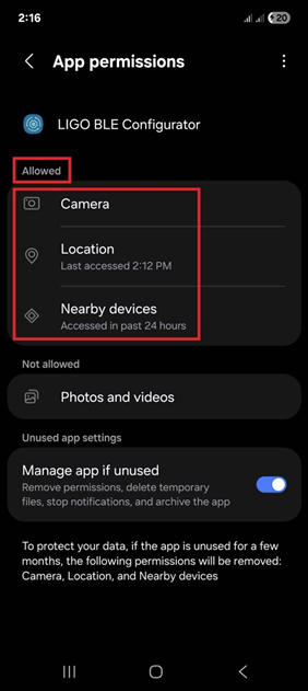 Figure 9. Grant all the permissions request by program
 -
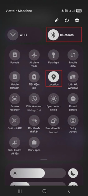 Figure 10. Grant all the permissions request by program


Grant all the permissions request by program as above
Connecting sensor
Run the application and select the sensor you want to connect to, as shown in the pictures below:
-
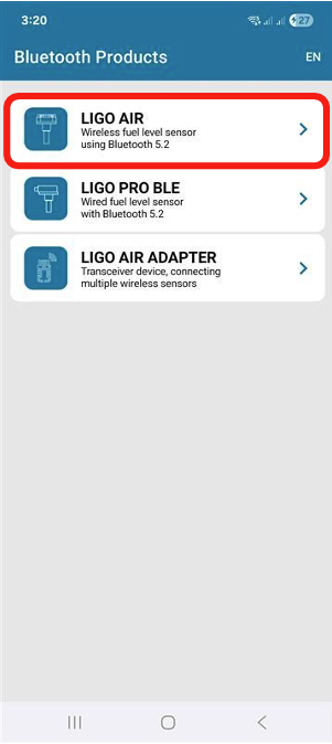 Figure 11. Selecting sensor type
 -
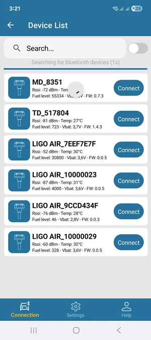 Figure 12. Connecting sensor


Set Empty and Set Full
Step 1: Set Full
- Immerse the sensor in fuel until the fuel reaches the sensor flange
- Wait for C_working value to stablize and then press Set Full button

Step 2: Set Empty
- Remove the sensor from the fuel and wait for 1-2 minutes allow the fuel drain from the measuring probe and then press Set Empty button.

Calibration table
After installation, the sensor must be calibrated to ensure accurate volume measurement. Calibration table can be performed either on the platform (server) or locally on the sensor.
- Calibration table on the Platform (Server): The sensor sends raw level values (ranging from 0 to 4095) to the server via the telematic device. The platform uses a calibration table to convert these values into volume (liters).
- Calibration table on the Sensor: The sensor directly sends volume values (liters) based on the internal calibration table.
Note: For LIGO AIR sensors, the manufacturer recommends performing calibration table on the platform.
Operation
Solutions for long-range or in metal-obstructed environments
In some cases, when the distance between the sensor and the receiver is long or there are many metal obstacles causing signal attenuation, customers can choose the LIGO AIR PRO model to increase transmission power or install the LIGO AIR Adapter at the receiver side to boost the signal received from the sensor.
Below is a comparison table of transmission distances between different types of sensors and receivers:
| Device | Bluetooth signal range |
|---|---|
| LIGO AIR + Telematics (tracker) device | Standard distance |
| LIGO AIR + LIGO AIR Adapter | 2 x Standard distance |
| LIGO AIR Pro + LIGO AIR Adapter | 4 x Standard distance |
Troubleshooting
| Symptom | Possible Cause | Solution |
|---|---|---|
| Sensor not discovered by LIGO BLE Configurator app |
|
|
| RSSI at receiver below −80 dBm |
|
|
| Reading shows 0% after Set Empty when fuel is present |
|
|
| Cannot connect with default password (login refused) |
|
|
If the problem persists, contact Support.
Maintenance
Certification / Compliance
Refer to LIGO AIR Certification & Approvals for current certificate status.
Support / Contact
| Channel | Detail |
|---|---|
| Company | SOJI ELECTRONICS.,JSC |
| Address | C50-LK13, Lot No. 09, New Urban Area, Le Trong Tan street, Duong Noi Ward, Ha Dong District, Hanoi City, Vietnam |
| Tel/Fax | +84 24 62 932 369 |
| contact@sojielectronics.com | |
| Website | sojielectronics.com |
Revision History
Loading revision history...