
LIGO AIR ADAPTER User Guide: Difference between revisions
| [checked revision] | [checked revision] |
Create page |
change content |
||
| (94 intermediate revisions by the same user not shown) | |||
| Line 1: | Line 1: | ||
== Safety Information == | == Safety Information == | ||
{{Notice | |||
| title = Important notes during sensor installation | |||
| body = Read and understand all safety information in this document before installing, operating or servicing the LIGO AIR ADAPTER | |||
*Keep the device out of the reach of children. It is not a toy and contains small parts. | |||
*Do not modify, drill or otherwise alter the device. | |||
*Always '''disconnect power''' before wiring, connecting/disconnecting cables or servicing. | |||
*Connect the device only to a power source within the rated input voltage. | |||
}} | |||
== Product Overview == | |||
=== Scope === | |||
This document provides instructions for installation, configuration, operation, and basic troubleshooting of the LIGO AIR ADAPTER. | |||
It is intended for system integrators, installers, and technical personnel involved in fuel monitoring and GPS telematics systems. | |||
== Product Overview == | === Product Overview === | ||
LIGO AIR ADAPTER is a communication and aggregation product designed to connect Ligo Air/Ligo Air Pro wireless fuel level sensors to GPS trackers that do not support BLE communication. | |||
The device acts as: | |||
* | * A BLE to wired protocol bridge. | ||
* A Sensor Union Module (SUM) capable of aggregating data from multiple sensors. | |||
* | * A BLE signal receiver with enhanced sensitivity for extended wireless range. | ||
* | |||
LIGO AIR ADAPTER supports multiple output interfaces including RS232, RS485, and AF, ensuring compatibility with a wide range of GPS tracking devices. | |||
=== Wiring diagram === | |||
<div style="text-align:center;"> | |||
[[File:System architecture1.png|frameless|1150px]] | |||
<div style="font-style:italic; color:#555;">Figure 1. LIGO AIR ADAPTER — Wiring diagram</div> | |||
</div> | </div> | ||
* Wireless fuel sensors (Ligo Air / Ligo Air Pro) transmit fuel level data via BLE. | |||
* LIGO AIR ADAPTER receives BLE data and processes it. | |||
* Processed data is transmitted to the GPS tracker via RS232, RS485 or AF interface. | |||
* Log sensor data for history view and troubleshooting. | |||
== Package Contents == | == Package Contents == | ||
<div class=" | {| class="wikitable" | ||
|+ Table 1. LIGO AIR ADAPTER — Package content | |||
!No. | |||
!Description | |||
!Qty (pcs) | |||
|- | |||
|1 | |||
|LIGO AIR ADAPTER | |||
|01 | |||
|- | |||
|2 | |||
|Quick user guide | |||
|01 | |||
|} | |||
== Specifications == | |||
{| class="wikitable" style="text-align:center;" | |||
|+ Table 2. LIGO AIR ADAPTER — Detail specifications | |||
| valign="top" |'''No.''' | |||
| valign="top" |'''PARAMETERS''' | |||
| valign="top" |'''RS232''' | |||
| valign="top" |'''RS485''' | |||
| valign="top" |'''PRO''' | |||
| valign="top" |'''AF''' | |||
|- | |||
| valign="top" |1 | |||
| valign="top" style="text-align:left;" |Dimension (without wire), mm | |||
| colspan="4" valign="top" |67x80 | |||
|- | |||
| valign="top" |2 | |||
| valign="top" style="text-align:left;" |Output interface | |||
| colspan="2" valign="top" |Digital | |||
| valign="top" |Analog & Digital | |||
| valign="top" |Analog | |||
|- | |||
| valign="top" |3 | |||
| valign="top" style="text-align:left;" |Baud rate, bit/sec | |||
| colspan="3" valign="top" |2400, 4800, 9600, 14400, 19200, 38400, 115200. | |||
| valign="top" | | |||
|- | |||
| valign="top" |4 | |||
| valign="top" style="text-align:left;" |Power supply, VDC | |||
| colspan="4" valign="top" |7 – 36 VDC | |||
|- | |||
| valign="top" |5 | |||
| valign="top" style="text-align:left;" |Maximum power consumption | |||
| colspan="4" valign="top" |~15 mA @13.5VDC | |||
|- | |||
| valign="top" |6 | |||
| valign="top" style="text-align:left;" |Power supply protection | |||
| colspan="4" valign="top" |1000VDC reverse polarity protection | |||
|- | |||
| valign="top" |7 | |||
| valign="top" style="text-align:left;" |Operating temperature, °C | |||
| colspan="4" valign="top" |-40 to 85 °C | |||
|- | |||
| valign="top" |8 | |||
| valign="top" style="text-align:left;" |Waterproof standard | |||
| colspan="4" valign="top" |IP67 | |||
|- | |||
| valign="top" |9 | |||
| valign="top" style="text-align:left;" |Output value range | |||
| colspan="2" valign="top" |Digital | |||
| valign="top" |Digital and analog | |||
| valign="top" |Analog (0-10V) | |||
|- | |||
| valign="top" |10 | |||
| valign="top" style="text-align:left;" |Data output mode | |||
| colspan="4" valign="top" |SUM, AVERAGE, INDIVIDUAL | |||
|- | |||
| valign="top" |11 | |||
| valign="top" style="text-align:left;" |Bluetooth specs | |||
| colspan="4" valign="top" |BLE 5.2 | |||
|- | |||
| valign="top" |12 | |||
| valign="top" style="text-align:left;" |Average service life, years (expected) | |||
| colspan="4" valign="top" |8 years | |||
|} | |||
== Installation == | |||
=== Hardware description and installation === | |||
==== Cable and wire definition ==== | |||
{| class="wikitable" style="text-align:center;" | |||
|+ Table 3. LIGO AIR ADAPTER — Cable description | |||
! No. !! Wire Color !! Wire Name !! Description | |||
|- | |||
| 1 || <div style="display:flex;align-items:center;justify-content:center;gap:8px;"><span style="display:inline-block;width:32px;height:14px;background:#f00;border:1px solid #999;"></span><span style="min-width:60px;text-align:left;font-weight:bold;">RED</span></div>|| '''VCC'''|| style="text-align:left;" | Power supply (7–36 V DC) | |||
|- | |||
| 2 || <div style="display:flex;align-items:center;justify-content:center;gap:8px;"><span style="display:inline-block;width:32px;height:14px;background:#fff;border:1px solid #999;"></span><span style="min-width:60px;text-align:left;font-weight:bold;">WHITE</span></div>|| '''AF'''|| style="text-align:left;" | Analog output (0–10 V) | |||
|- | |||
| 3 || <div style="display:flex;align-items:center;justify-content:center;gap:8px;"><span style="display:inline-block;width:32px;height:14px;background:#000;"></span><span style="min-width:60px;text-align:left;font-weight:bold;">BLACK</span></div>|| '''GND'''|| style="text-align:left;" | Ground | |||
|- | |||
| 4 || <div style="display:flex;align-items:center;justify-content:center;gap:8px;"><span style="display:inline-block;width:32px;height:14px;background:#2e8b2e;"></span><span style="min-width:60px;text-align:left;font-weight:bold;">GREEN</span></div>|| '''RS485-B'''|| style="text-align:left;" | Signal wire B for RS485 | |||
|- | |||
| 5 || <div style="display:flex;align-items:center;justify-content:center;gap:8px;"><span style="display:inline-block;width:32px;height:14px;background:#f4d03f;"></span><span style="min-width:60px;text-align:left;font-weight:bold;">YELLOW</span></div>|| '''RS485-A'''|| style="text-align:left;" | Signal wire A for RS485 | |||
|- | |||
| 6 || <div style="display:flex;align-items:center;justify-content:center;gap:8px;"><span style="display:inline-block;width:32px;height:14px;background:#000;"></span><span style="min-width:60px;text-align:left;font-weight:bold;">BLACK</span></div>|| '''GND'''|| style="text-align:left;" | Ground | |||
|- | |||
| 7 || <div style="display:flex;align-items:center;justify-content:center;gap:8px;"><span style="display:inline-block;width:32px;height:14px;background:#7b3f00;"></span><span style="min-width:60px;text-align:left;font-weight:bold;">BROWN</span></div>|| '''RS232-RX'''|| style="text-align:left;" | Input data for RS232 | |||
|- | |||
| 8 || <div style="display:flex;align-items:center;justify-content:center;gap:8px;"><span style="display:inline-block;width:32px;height:14px;background:#1e6cff;"></span><span style="min-width:60px;text-align:left;font-weight:bold;">BLUE</span></div> || '''RS232-TX''' || style="text-align:left;" | Output data for RS232 | |||
|} | |||
==== Mechanical installation ==== | |||
* Install Ligo Adapter inside the vehicle cabin or protected enclosure | |||
* Avoid direct exposure to water, excessive heat, or strong electromagnetic sources | |||
* Ensure sufficient distance from high-current cables when possible | |||
==== Electrical connection ==== | |||
Connect the selected communication interface to the GPS tracker following the table below: | |||
{| class="wikitable" style="text-align:center;" | |||
|+ Table 4. LIGO AIR ADAPTER — Wiring connection | |||
! No. !! Wire Name !! RS232 !! RS485 !! AF !! PRO | |||
|- | |||
| 1 || '''VCC''' || ✓ || ✓ || ✓ || ✓ | |||
|- | |||
| 2 || '''AF''' || — || — || ✓ || ✓ | |||
|- | |||
| 3 || '''GND''' || ✓ || ✓ || ✓ || ✓ | |||
|- | |||
| 4 || '''RS485-B''' || — || ✓ || — || ✓ | |||
|- | |||
| 5 || '''RS485-A''' || — || ✓ || — || ✓ | |||
|- | |||
| 6 || '''GND''' || ✓ || ✓ || ✓ || ✓ | |||
|- | |||
| 7 || '''RS232-RX''' || ✓ || — || — || ✓ | |||
|- | |||
| 8 || '''RS232-TX''' || ✓ || — || — || ✓ | |||
|} | |||
{{Notice | |||
| title = Output Protocol Compatibility — RS232 / RS485 / AF | |||
| body = The PRO model supports all available output communication protocols (RS232, RS485 and AF). Select the output interface compatible with the existing GPS tracker. | |||
}} | |||
=== LED Status Indication === | |||
The Ligo Adapter is equipped with a status LED to indicate its current operating state. | |||
{| class="wikitable" | |||
|+ Table 5. LIGO AIR ADAPTER — LED status | |||
! LED Status !! Description | |||
|- | |||
| style="text-align:center;" | Red blinking || No sensor is paired with the adapter | |||
|- | |||
| style="text-align:center;" | Red solid || Sensor(s) paired, but no data is being received | |||
|- | |||
| style="text-align:center;" | Green solid || Valid data is being received from paired sensor(s) | |||
|} | |||
== Configuration == | |||
=== Software configuration === | |||
LIGO AIR ADAPTER is configured using Ligo BLE Configurator. Please download and install it from Play Store on android OS or App Store on IOS before starting configurations. | |||
The software is structured into three main sections, each serving a specific purpose in the installation, operation and troubleshooting as these below figures. | |||
== | <gallery mode="packed" widths="250" heights="500"> | ||
< | File:LIGO-BLE-Adapter-fig2-connection-section.png|Figure 2. Connection section | ||
File:LIGO-BLE-Adapter-fig3-settings-section.png|Figure 3. Settings section | |||
File:LIGO-BLE-Adapter-fig4-help-section.png|Figure 4. Help section | |||
</gallery> | |||
<div style="display:flex; gap:30px; flex-wrap:wrap; align-items:flex-start;"> | |||
<div style="flex:1; min-width:260px;"> | |||
<div style="font-size:1.2em; font-weight:bold; color:#0054A6; border-bottom:2px solid #eaecf0; padding-bottom:5px; margin-bottom:10px;">Connection section</div> | |||
This section provides general information and real-time status of the device. It allows users to quickly verify that the adapter is powered, accessible, and ready for configuration. | |||
''' | '''Included information:''' | ||
* | * Device name | ||
* | * Device MAC address and serial number | ||
* | * Firmware / Hardware version | ||
* Fuel data of paired sensors | |||
* Supply voltage and temperature | |||
* RSSI signal | |||
The Connection section allows users to quickly verify that the adapter is powered, accessible, and ready for configuration. | |||
</div> | </div> | ||
= | <div style="flex:1; min-width:260px;"> | ||
<div | <div style="font-size:1.2em; font-weight:bold; color:#0054A6; border-bottom:2px solid #eaecf0; padding-bottom:5px; margin-bottom:10px;">Settings section</div> | ||
The Settings section contains all configuration parameters related to sensor pairing, output interfaces, and data type. It is intended for device setup and integration with GPS tracking devices. | |||
'' | '''Key configuration functions:''' | ||
* Sensor pairing management (add / remove sensors using MAC address) | |||
* Output interface configuration (RS232, RS485, AF) | |||
* Communication protocol | |||
* Data mode selection (SUM, AVERAGE, INDIVIDUAL) | |||
* Data log configuration and viewing | |||
* Installation report generation | |||
</div> | |||
<div style="flex:1; min-width:260px;"> | |||
<div style="font-size:1.2em; font-weight:bold; color:#0054A6; border-bottom:2px solid #eaecf0; padding-bottom:5px; margin-bottom:10px;">Help section</div> | |||
The Support section provides technical assistance and software information. | |||
This section includes: | |||
* | * Software version | ||
* | * Technical support contact information | ||
* Reference documentation and troubleshooting resources | |||
* | |||
This section ensures that users can easily access assistance if necessary. | |||
</div> | |||
</div> | </div> | ||
=== Sensor pairing and configuration === | |||
== | ==== Sensor pairing ==== | ||
< | |||
Follow these steps to pair Ligo Air/Ligo Air Pro sensors with LIGO AIR ADAPTER | |||
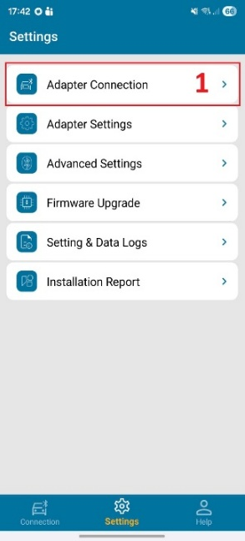
* Launch Ligo BLE Configurator application > Select LIGO AIR ADAPTER (the software auto scan nearby BLE Adapter) > press Connect button | |||
* Switch to Settings section to start pairing sensor to the LIGO AIR ADAPTER as Figure 4. | |||
<gallery mode="packed" widths="250" heights="500"> | |||
File:LIGO-Adapter-config-select-device.png|Step 1. Select device | |||
File:LIGO-Adapter-config-scan-sensor.png|Step 2. Scan sensors | |||
File:LIGO-Adapter-config-confirm-pairing.png|Step 3. Confirm pairing | |||
</gallery> | |||
==== Parameters configuration ==== | |||
<gallery mode="packed" widths="250" heights="500"> | |||
File:LIGO-Adapter-parameter-1.png|Parameters - page 1 | |||
File:LIGO-Adapter-parameter-2.png|Parameters - page 2 | |||
</gallery> | |||
{| class="wikitable" | |||
|- | |||
! No. !! Parameter !! Description | |||
|- | |||
| style="text-align:center;" | 1 || Message interval (1..60s) || Defines the time interval between two consecutive data transmissions from the LIGO AIR ADAPTER | |||
|- | |||
| style="text-align:center;" | 2 || Protocol || Selects the output communication protocol used to transmit fuel data to the GPS tracker. | |||
* SOJI protocol | |||
* LLS protocol | |||
|+ Table 6. LIGO AIR ADAPTER — Parameter descriptions | |||
| style="text-align:center;" | 3 || Automatic transmission mode || Defines the data transmission format. | |||
* HEX format | |||
* ASCII format | |||
|- | |||
| style="text-align:center;" | 4 || Baud rate || Sets the serial communication speed for RS232 or RS485 output. | |||
|- | |||
| style="text-align:center;" | 5 || Data mode || Defines how fuel data from multiple paired sensors is processed before transmission. | |||
* SUM: Total fuel value of all paired sensors | |||
* AVERAGE: Average fuel value of all paired sensors | |||
* INDIVIDUAL: Fuel data from each sensor is transmitted individually upon Modbus request. | |||
|- | |||
| style="text-align:center;" | 6 || Address (1-254) || Sets the Modbus address of the LIGO AIR ADAPTER. | |||
|- | |||
| style="text-align:center;" | 7 || Level min (0..8V) || Defines the minimum output voltage level for the AF output. | |||
|- | |||
| style="text-align:center;" | 8 || Level max (2..10V) || Defines the maximum output voltage level for the AF output. | |||
|- | |||
| style="text-align:center;" | 9 || Max volume || Defines the maximum digital fuel level resolution used for data transmission. | |||
* 1023: 10-bit resolution. | |||
* 4095: 12-bit resolution. | |||
|} | |||
== Operation == | == Operation == | ||
=== Data log and settings log === | |||
==== Data log ==== | |||
<gallery mode="packed" widths="250" heights="500"> | |||
File:LIGO-Adapter-open-log.png|Step 1. Open log | |||
File:LIGO-Adapter-select-period.png|Step 2. Select period | |||
File:LIGO-Adapter-view-data.png|Step 3. View data | |||
</gallery> | |||
The Data Log function allows users to view historical fuel level data received from paired sensors over time. | |||
The log records: | |||
* Timestamp of received data | |||
* Fuel level values from paired sensors | |||
* RSSI signal | |||
* Temperature of sensor | |||
This function is used for: | |||
* System verification during installation | |||
* Diagnostic and troubleshooting purposes | |||
* Validation of sensor communication stability | |||
The user can select a time period (Today, Yesterday, Week, Month, or a Custom Period) and then press the Download button to retrieve the data log, as shown in Figure 6. | |||
The retrieved data log is displayed in the Log Display Area. | |||
==== Settings log ==== | |||
</ | <gallery mode="packed" widths="250" heights="500"> | ||
File:LIGO-Adapter-open-setting-log.png|Step 1. Open settings log | |||
File:LIGO-Adapter-select-source.png|Step 2. Select source | |||
File:LIGO-Adapter-view-setting-log.png|Step 3. View log | |||
</gallery> | |||
The Settings Log function allows users to review the historical configuration records of the LIGO AIR ADAPTER. | |||
This log stores all parameter changes previously configured by the user, enabling traceability and verification of device setup. | |||
The user can select the Log source (data from EEPROM or data on the server), and the settings log will be displayed in the Log Display Area, as shown in Figure 7. | |||
==== Report ==== | |||
<div style="display:flex; gap:30px; align-items:flex-start; flex-wrap:wrap;"> | |||
<div style="flex:1; min-width:280px;"> | |||
<div style="font-size:1.1em; font-weight:bold; color:#0054A6;">Installation Report</div> | |||
Each installation report includes: | |||
*Installer Name | |||
*Installation Date and Time | |||
*Serial Number of Adapter (SN) | |||
*Model: Vehicle Information | |||
*Plate number: License of vehicle | |||
*Other information | |||
*Real installation photos captured via mobile device | |||
</div> | |||
<div> | |||
<div style="text-align:center;"> | |||
[[File:install-report.png|frameless|284px]] | |||
<div style="font-style:italic; color:#555;">Figure 9. Installation report</div> | |||
</div> | |||
</div> | |||
</div> | </div> | ||
== | <div style="display:flex; gap:30px; align-items:flex-start; flex-wrap:wrap;"> | ||
<div | <div style="flex:1; min-width:280px;"> | ||
<div style="font-size:1.1em; font-weight:bold; color:#0054A6;">Maintenance Report</div> | |||
Each maintenance report includes: | |||
*Installer Name | |||
*Maintenance Date and Time | |||
*Serial Number of Adapter (SN) | |||
*Model: Vehicle Information | |||
*Plate number: License of vehicle | |||
*Other information | |||
*Real installation photos captured via mobile device | |||
</div> | |||
<div> | |||
<div style="text-align:center;"> | |||
[[File:maintance-report.png|frameless|284px]] | |||
<div style="font-style:italic; color:#555;">Figure 10. Maintenance report</div> | |||
</div> | |||
</div> | |||
</div> | |||
<div style="display:flex; gap:30px; align-items:flex-start; flex-wrap:wrap;"> | |||
<div style="flex:1; min-width:280px;"> | |||
<div style="font-size:1.1em; font-weight:bold; color:#0054A6;">View Report</div> | |||
The View Report function allows users to review installation and maintenance history at any time. | |||
Steps to open reports: | |||
''' | * '''Open View Report''' in the Ligo BLE Configurator App. | ||
* | * '''Enter the Adapter Serial Number (SN)''' and press the Search button. | ||
The system displays: | |||
*Installation reports | |||
*Maintenance reports | |||
</div> | |||
<div> | |||
<div style="text-align:center;"> | |||
[[File:view-report.png|frameless|284px]] | |||
<div style="font-style:italic; color:#555;">Figure 11. View report</div> | |||
</div> | |||
</div> | |||
</div> | </div> | ||
== Troubleshooting == | |||
{| class="wikitable" | |||
|+ Table 7. LIGO AIR ADAPTER — Troubleshooting | |||
! Issue !! Possible Cause !! Recommended Action | |||
|- | |||
| No data on GPS || Incorrect wiring || Verify interface wiring | |||
|- | |||
| Sensor not detected || MAC address not added, wrong MAC address || Reconfigure sensor list | |||
|- | |||
| Unstable data || BLE signal attenuation || Reposition adapter | |||
|- | |||
| Incorrect fuel value || Wrong data mode || Check SUM / AVERAGE setting | |||
|} | |||
== Certification / Compliance == | |||
Refer to [[LIGO AIR ADAPTER Certification & Approvals]] for current certificate status.'' | |||
== Support / Contact == | == Support / Contact == | ||
{| class="wikitable" | |||
|+ Table 9. LIGO AIR ADAPTER — Support/ Contact | |||
! Channel !! Detail | |||
|- | |||
| Company || SOJI ELECTRONICS.,JSC | |||
|- | |||
| Address || C50-LK13, Lot No. 09, New Urban Area, Le Trong Tan street, Duong Noi Ward, Ha Dong District, Hanoi City, Vietnam | |||
|- | |||
| Tel/Fax || +84 24 62 932 369 | |||
|- | |||
| Email || contact@sojielectronics.com | |||
|- | |||
| Website || [http://sojielectronics.com sojielectronics.com] | |||
|} | |||
<div class="noprint"> | |||
== Related Documents == | == Related Documents == | ||
''Cross-references to other documents.'' | ''Cross-references to other documents.'' | ||
| Line 188: | Line 462: | ||
</div> | </div> | ||
[[Category:LIGO | [[Category:LIGO AIR ADAPTER ]] | ||
Latest revision as of 00:47, 6 July 2026
Safety Information
| ℹ️ NOTICE — Important notes during sensor installation |
|---|
|
Read and understand all safety information in this document before installing, operating or servicing the LIGO AIR ADAPTER
|
Product Overview
Scope
This document provides instructions for installation, configuration, operation, and basic troubleshooting of the LIGO AIR ADAPTER.
It is intended for system integrators, installers, and technical personnel involved in fuel monitoring and GPS telematics systems.
Product Overview
LIGO AIR ADAPTER is a communication and aggregation product designed to connect Ligo Air/Ligo Air Pro wireless fuel level sensors to GPS trackers that do not support BLE communication.
The device acts as:
- A BLE to wired protocol bridge.
- A Sensor Union Module (SUM) capable of aggregating data from multiple sensors.
- A BLE signal receiver with enhanced sensitivity for extended wireless range.
LIGO AIR ADAPTER supports multiple output interfaces including RS232, RS485, and AF, ensuring compatibility with a wide range of GPS tracking devices.
Wiring diagram

- Wireless fuel sensors (Ligo Air / Ligo Air Pro) transmit fuel level data via BLE.
- LIGO AIR ADAPTER receives BLE data and processes it.
- Processed data is transmitted to the GPS tracker via RS232, RS485 or AF interface.
- Log sensor data for history view and troubleshooting.
Package Contents
| No. | Description | Qty (pcs) |
|---|---|---|
| 1 | LIGO AIR ADAPTER | 01 |
| 2 | Quick user guide | 01 |
Specifications
| No. | PARAMETERS | RS232 | RS485 | PRO | AF |
| 1 | Dimension (without wire), mm | 67x80 | |||
| 2 | Output interface | Digital | Analog & Digital | Analog | |
| 3 | Baud rate, bit/sec | 2400, 4800, 9600, 14400, 19200, 38400, 115200. | |||
| 4 | Power supply, VDC | 7 – 36 VDC | |||
| 5 | Maximum power consumption | ~15 mA @13.5VDC | |||
| 6 | Power supply protection | 1000VDC reverse polarity protection | |||
| 7 | Operating temperature, °C | -40 to 85 °C | |||
| 8 | Waterproof standard | IP67 | |||
| 9 | Output value range | Digital | Digital and analog | Analog (0-10V) | |
| 10 | Data output mode | SUM, AVERAGE, INDIVIDUAL | |||
| 11 | Bluetooth specs | BLE 5.2 | |||
| 12 | Average service life, years (expected) | 8 years | |||
Installation
Hardware description and installation
Cable and wire definition
| No. | Wire Color | Wire Name | Description |
|---|---|---|---|
| 1 | RED |
VCC | Power supply (7–36 V DC) |
| 2 | WHITE |
AF | Analog output (0–10 V) |
| 3 | BLACK |
GND | Ground |
| 4 | GREEN |
RS485-B | Signal wire B for RS485 |
| 5 | YELLOW |
RS485-A | Signal wire A for RS485 |
| 6 | BLACK |
GND | Ground |
| 7 | BROWN |
RS232-RX | Input data for RS232 |
| 8 | BLUE |
RS232-TX | Output data for RS232 |
Mechanical installation
- Install Ligo Adapter inside the vehicle cabin or protected enclosure
- Avoid direct exposure to water, excessive heat, or strong electromagnetic sources
- Ensure sufficient distance from high-current cables when possible
Electrical connection
Connect the selected communication interface to the GPS tracker following the table below:
| No. | Wire Name | RS232 | RS485 | AF | PRO |
|---|---|---|---|---|---|
| 1 | VCC | ✓ | ✓ | ✓ | ✓ |
| 2 | AF | — | — | ✓ | ✓ |
| 3 | GND | ✓ | ✓ | ✓ | ✓ |
| 4 | RS485-B | — | ✓ | — | ✓ |
| 5 | RS485-A | — | ✓ | — | ✓ |
| 6 | GND | ✓ | ✓ | ✓ | ✓ |
| 7 | RS232-RX | ✓ | — | — | ✓ |
| 8 | RS232-TX | ✓ | — | — | ✓ |
| ℹ️ NOTICE — Output Protocol Compatibility — RS232 / RS485 / AF |
|---|
|
The PRO model supports all available output communication protocols (RS232, RS485 and AF). Select the output interface compatible with the existing GPS tracker. |
LED Status Indication
The Ligo Adapter is equipped with a status LED to indicate its current operating state.
| LED Status | Description |
|---|---|
| Red blinking | No sensor is paired with the adapter |
| Red solid | Sensor(s) paired, but no data is being received |
| Green solid | Valid data is being received from paired sensor(s) |
Configuration
Software configuration
LIGO AIR ADAPTER is configured using Ligo BLE Configurator. Please download and install it from Play Store on android OS or App Store on IOS before starting configurations.
The software is structured into three main sections, each serving a specific purpose in the installation, operation and troubleshooting as these below figures.
-
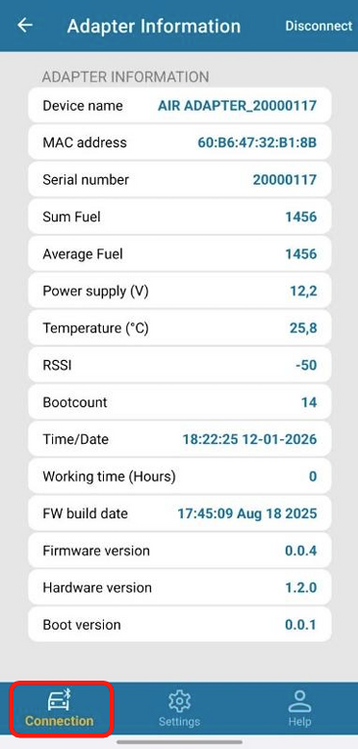 Figure 2. Connection section
 -
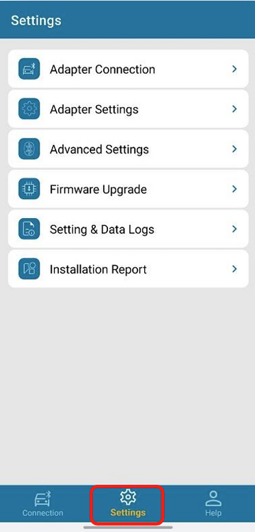 Figure 3. Settings section
 -
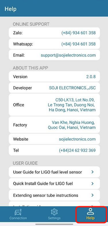 Figure 4. Help section


This section provides general information and real-time status of the device. It allows users to quickly verify that the adapter is powered, accessible, and ready for configuration.
Included information:
- Device name
- Device MAC address and serial number
- Firmware / Hardware version
- Fuel data of paired sensors
- Supply voltage and temperature
- RSSI signal
The Connection section allows users to quickly verify that the adapter is powered, accessible, and ready for configuration.
The Settings section contains all configuration parameters related to sensor pairing, output interfaces, and data type. It is intended for device setup and integration with GPS tracking devices.
Key configuration functions:
- Sensor pairing management (add / remove sensors using MAC address)
- Output interface configuration (RS232, RS485, AF)
- Communication protocol
- Data mode selection (SUM, AVERAGE, INDIVIDUAL)
- Data log configuration and viewing
- Installation report generation
The Support section provides technical assistance and software information.
This section includes:
- Software version
- Technical support contact information
- Reference documentation and troubleshooting resources
This section ensures that users can easily access assistance if necessary.
Sensor pairing and configuration
Sensor pairing
Follow these steps to pair Ligo Air/Ligo Air Pro sensors with LIGO AIR ADAPTER
- Launch Ligo BLE Configurator application > Select LIGO AIR ADAPTER (the software auto scan nearby BLE Adapter) > press Connect button
- Switch to Settings section to start pairing sensor to the LIGO AIR ADAPTER as Figure 4.
-
 Step 1. Select device
 -
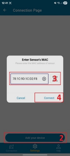 Step 2. Scan sensors
 -
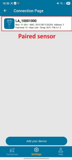 Step 3. Confirm pairing


Parameters configuration
-
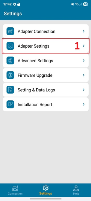 Parameters - page 1
 -
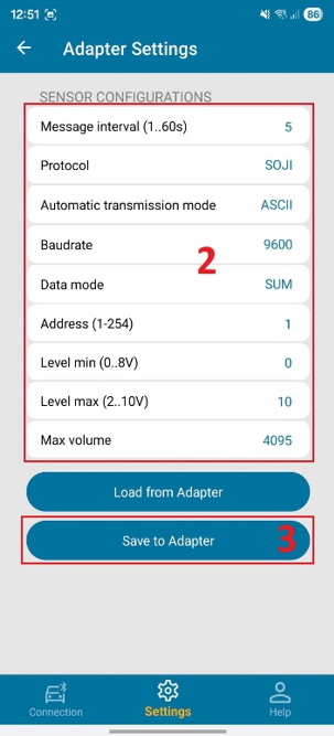 Parameters - page 2


| No. | Parameter | Description |
|---|---|---|
| 1 | Message interval (1..60s) | Defines the time interval between two consecutive data transmissions from the LIGO AIR ADAPTER |
| 2 | Protocol | Selects the output communication protocol used to transmit fuel data to the GPS tracker.
|
| 3 | Automatic transmission mode | Defines the data transmission format.
|
| 4 | Baud rate | Sets the serial communication speed for RS232 or RS485 output. |
| 5 | Data mode | Defines how fuel data from multiple paired sensors is processed before transmission.
|
| 6 | Address (1-254) | Sets the Modbus address of the LIGO AIR ADAPTER. |
| 7 | Level min (0..8V) | Defines the minimum output voltage level for the AF output. |
| 8 | Level max (2..10V) | Defines the maximum output voltage level for the AF output. |
| 9 | Max volume | Defines the maximum digital fuel level resolution used for data transmission.
|
Operation
Data log and settings log
Data log
-
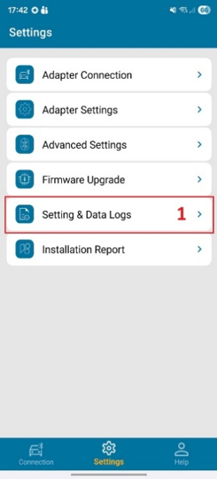 Step 1. Open log
 -
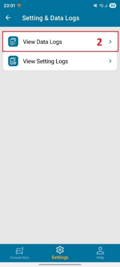 Step 2. Select period
 -
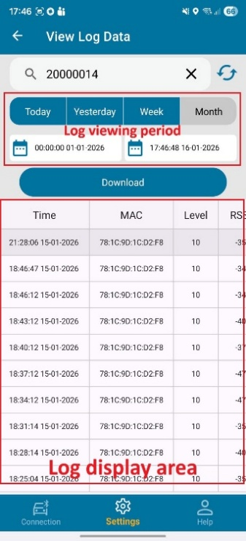 Step 3. View data


The Data Log function allows users to view historical fuel level data received from paired sensors over time.
The log records:
- Timestamp of received data
- Fuel level values from paired sensors
- RSSI signal
- Temperature of sensor
This function is used for:
- System verification during installation
- Diagnostic and troubleshooting purposes
- Validation of sensor communication stability
The user can select a time period (Today, Yesterday, Week, Month, or a Custom Period) and then press the Download button to retrieve the data log, as shown in Figure 6.
The retrieved data log is displayed in the Log Display Area.
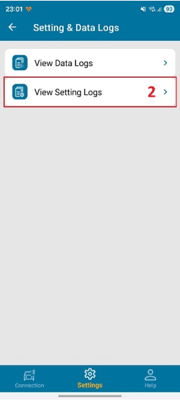
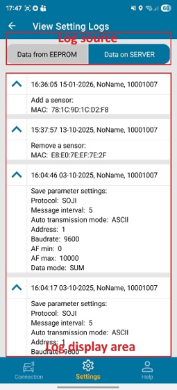
Settings log
-
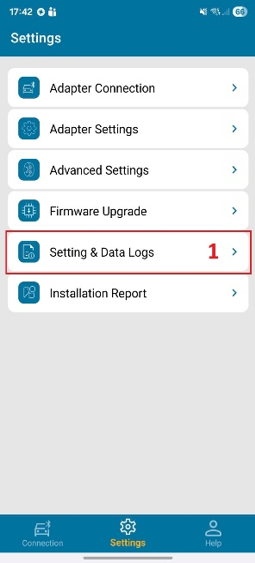 Step 1. Open settings log
 -
 Step 2. Select source
 -
 Step 3. View log


The Settings Log function allows users to review the historical configuration records of the LIGO AIR ADAPTER.
This log stores all parameter changes previously configured by the user, enabling traceability and verification of device setup.
The user can select the Log source (data from EEPROM or data on the server), and the settings log will be displayed in the Log Display Area, as shown in Figure 7.
Report
Each installation report includes:
- Installer Name
- Installation Date and Time
- Serial Number of Adapter (SN)
- Model: Vehicle Information
- Plate number: License of vehicle
- Other information
- Real installation photos captured via mobile device

Each maintenance report includes:
- Installer Name
- Maintenance Date and Time
- Serial Number of Adapter (SN)
- Model: Vehicle Information
- Plate number: License of vehicle
- Other information
- Real installation photos captured via mobile device

The View Report function allows users to review installation and maintenance history at any time.
Steps to open reports:
- Open View Report in the Ligo BLE Configurator App.
- Enter the Adapter Serial Number (SN) and press the Search button.
The system displays:
- Installation reports
- Maintenance reports

Troubleshooting
| Issue | Possible Cause | Recommended Action |
|---|---|---|
| No data on GPS | Incorrect wiring | Verify interface wiring |
| Sensor not detected | MAC address not added, wrong MAC address | Reconfigure sensor list |
| Unstable data | BLE signal attenuation | Reposition adapter |
| Incorrect fuel value | Wrong data mode | Check SUM / AVERAGE setting |
Certification / Compliance
Refer to LIGO AIR ADAPTER Certification & Approvals for current certificate status.
Support / Contact
| Channel | Detail |
|---|---|
| Company | SOJI ELECTRONICS.,JSC |
| Address | C50-LK13, Lot No. 09, New Urban Area, Le Trong Tan street, Duong Noi Ward, Ha Dong District, Hanoi City, Vietnam |
| Tel/Fax | +84 24 62 932 369 |
| contact@sojielectronics.com | |
| Website | sojielectronics.com |
Revision History
Loading revision history...