
LIGO PRO BLE User Guide: Difference between revisions
| [checked revision] | [checked revision] |
Initial Release [release] |
|||
| (2 intermediate revisions by the same user not shown) | |||
| Line 190: | Line 190: | ||
<div style="text-align:center;"> | <div style="text-align:center;"> | ||
[[File: | [[File:RS232-RS485.jpg|frameless|756x756px]] | ||
<div style="font-style:italic; color:#555;">Figure 13. Wiring diagram of RS232 and RS485 output signals</div> | <div style="font-style:italic; color:#555;">Figure 13. Wiring diagram of RS232 and RS485 output signals</div> | ||
</div> | </div> | ||
| Line 199: | Line 199: | ||
| <div style="display:flex;align-items:center;justify-content:center;gap:8px;"><span style="display:inline-block;width:32px;height:14px;background:#000;"></span><span style="min-width:60px;text-align:left;font-weight:bold;">Black</span></div> || style="text-align:left;" | GND (Ground) (V-) | | <div style="display:flex;align-items:center;justify-content:center;gap:8px;"><span style="display:inline-block;width:32px;height:14px;background:#000;"></span><span style="min-width:60px;text-align:left;font-weight:bold;">Black</span></div> || style="text-align:left;" | GND (Ground) (V-) | ||
|- | |- | ||
| <div style="display:flex;align-items:center;justify-content:center;gap:8px;"><span style="display:inline-block;width:32px;height:14px;background:# | | <div style="display:flex;align-items:center;justify-content:center;gap:8px;"><span style="display:inline-block;width:32px;height:14px;background:#3b8dd9;"></span><span style="min-width:60px;text-align:left;font-weight:bold;">Blue</span></div> || style="text-align:left;" | TXD/B- | ||
|- | |- | ||
| <div style="display:flex;align-items:center;justify-content:center;gap:8px;"><span style="display:inline-block;width:32px;height:14px;background:# | | <div style="display:flex;align-items:center;justify-content:center;gap:8px;"><span style="display:inline-block;width:32px;height:14px;background:#f4d03f;"></span><span style="min-width:60px;text-align:left;font-weight:bold;">Yellow</span></div> || style="text-align:left;" | RXD/A+ | ||
|- | |- | ||
| <div style="display:flex;align-items:center;justify-content:center;gap:8px;"><span style="display:inline-block;width:32px;height:14px;background:#d63a3a;"></span><span style="min-width:60px;text-align:left;font-weight:bold;">Red</span></div> || style="text-align:left;" | | | <div style="display:flex;align-items:center;justify-content:center;gap:8px;"><span style="display:inline-block;width:32px;height:14px;background:#d63a3a;"></span><span style="min-width:60px;text-align:left;font-weight:bold;">Red</span></div> || style="text-align:left;" | 6 - 40 VDC | ||
|} | |} | ||
| Line 291: | Line 291: | ||
Note: For LIGO AIR sensors, the manufacturer recommends performing calibration table on the platform. | Note: For LIGO AIR sensors, the manufacturer recommends performing calibration table on the platform. | ||
=== Attention! === | === Attention! === | ||
| Line 333: | Line 327: | ||
<span class="dim">Loading revision history...</span> | <span class="dim">Loading revision history...</span> | ||
</div> | </div> | ||
[[Category:LIGO PRO BLE ]] | [[Category:LIGO PRO BLE ]] | ||
Latest revision as of 03:16, 11 August 2026
Safety Information
| ℹ️ NOTICE — Installer Qualifications and Safety |
|---|
|
Product Overview
LIGO PRO BLE sensor is produced and developed by SOJI Electronics Join Stock Company. The device is designed to measure the level of liquid fuels and other non-conductive liquids in vehicle's tanks and stationary fuel storages, applicable in different fields. The measured values will be t transformed into output signal in the form of: Analog, Frequency, RS232, RS485… and transmitted to a connected external device
Under particular conditions, the device can reach a high accuracy up to 99.5%. At present, on the market there are several lines of sensor using different technologies to measure fuel level such as: magnetically operated switches (reed switches), ultrasound wave (ultrasonic sensor), capacitive sensing (capacitive sensor). Among these ones, capacitive sensing technology is considered to have highest accuracy and greatest lifespan.
Package Contents
10 main items with specific quantities are described below:
| No. | Description | Qty (pcs) |
|---|---|---|
| 1 | LIGO Fuel Level Sensor. Standard lengths: 700, 1000, and 1500mm (for other customized lengths, please contact the manufacturer) | 01 |
| 2 | Oil filter | 01 |
| 3 | Gasoline-resistant rubber gasket | 01 |
| 4 | Anti-vibration spring when moving | 01 |
| 5 | 1A Fuse protection | 01 |
| 6 | Self-drilling screw M4.8x32mm | 04 |
| 7 | Rivet and screw M5x20mm | 04 |
| 8 | Sealing wire | 02 |
| 9 | 7m signal wire | 01 |
| 10 | Quick installation manual | 01 |
Specifications
| Parameter | AF | RS232 | RS485 |
|---|---|---|---|
| Standard length (L), mm | 700, 1000, 1500...up to 6000 mm | ||
| Measuring error, % | ± 0.5 % | ||
| Output signal | Analog (0-9V) | RS232 | RS485 |
| Baud rate, bit/sec | 2400, 4800, 9600, 19200, 38400, 57600, 115200. | ||
| Power supply (DC input voltage, V) | 6-40V | ||
| Supply protection (Over-voltage 100 VDC for 2 minutes. Reverse polarity) | Yes | ||
| Maximum power consumption, mA | 20 | ||
| Waterproof standard (Ingress protection rating, IP) | IP69K | ||
| Operating temperature, °C | -40...+85 | ||
| Maximum allowed humidity level,% | 100 | ||
| Resolution, bit | 12 | ||
| Digital reading range corresponding to the minimum level measurement value | Analog (0...8V) | 0 | 0 |
| Digital reading range corresponding to the maximum level measurement value | Analog (1...9V) | 4095 | 4095 |
| Average sampling period, s | 0...255 | ||
| Message interval, s | Continuous | 1...255 | 1...255 |
| Absolute error in temperature measurement within the entire temperature measuring range, °С | ±1 | ||
| Bluetooth specs | Bluetooth 5.1, IEEE 802.15.4-2006, 2.4 GHz, -95 dBm sensitivity, +8 dBm TX Power | ||
| Average service life, years (expected) | 10 | 10 | 10 |
Installation
Selecting the location to install sensor
- Installation location should be as close as possible to the geometric center and placed at the deepest level of the tank.

- When being installed, the sensor should not be in contact with reinforcement ribs inside the tank

Drilling the hole on fuel tank
- Drill out the central bore by bimetal core drill ø38 mm

- Drill out four mounting holes according to the diagram:

The mounting hole diameter depends on the tank material:
- ø 4 mm – for metal tank with wall thickness over 3 mm (cut M5 self screw M4.8)

- ø 7 mm – for plastic and metal tank with wall thickness up to 3 mm (for rivets)


Measuaring the tank depth and cutting sensor'measuring probe

- Cut the sensor's measuring probe so that its length is 25 mm less than the depth of the tank. Ensure that shearing line is perpendicular to the sensor longitudinal axis

Notes: Minimum allowable length of the measuring probe is 150 mm.
Installing screen filter
Screen filter is mounted on the measuring probe of sensor to protect measuring probe electrodes from mud and water. Using the filter extends significantly faultless lifetime of the sensor.
Screen filter mounting order: firstly put on fixator, then put on bottom stop and fix it with two side screws. Put the screen filter over bottom stop and fasten it with a fixator locks.

Installing and connecting
- Applying oil-and-petrol resistant non-conductive sealant to ruber gasket

- Put the sensor into the tank and fix: when fixing with rivets, use a rivet driver when bolting, put on a seal (per bolt), a spacer and a spring washer when fixing to plastic tanks with wall thickness over 3 mm, use vendor furnished self-tapping screws and a seal (per self-tapping screw)

- Connect the sensors to an external device using 7m cable
The wire cable color:
RS232/RS485:

| Wire Color | Description |
|---|---|
Black |
GND (Ground) (V-) |
Blue |
TXD/B- |
Yellow |
RXD/A+ |
Red |
6 - 40 VDC |
AF:

| Wire Color | Description |
|---|---|
Black |
GND (Ground) (V-) |
Yellow |
Out (Analog/Frequency) |
Red |
15-37 VDC or 7.5-75V for SP PRO series |
- Connect the fuse holder to LIGO sensor power cable (brown wire) in close vicinity to the vehicle power supply circuit
- Installing the fuse in the fuse holder
Sealing
- Install the bolt through a hole in the seal.

Configuration
Connecting sensor to smartphone and setting
To configure the LIGO AIR fuel sensor, download the LIGO BLE Configurator app on Appstore (for IOS) or CH Play (for Android devices).
Hereinafter LIGO BLE Configurator is referred to as the "application" or "app".
Note: For full operation, you must grant all the permissions requested by the app
-
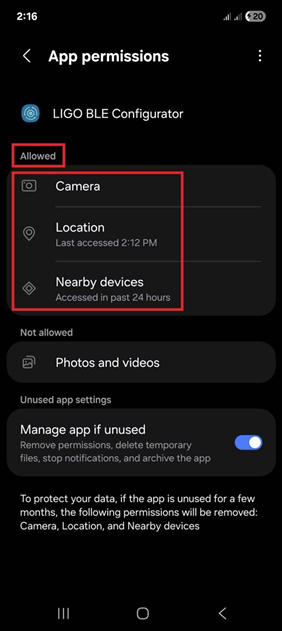 Figure 16. Grant all the permissions request by program
 -
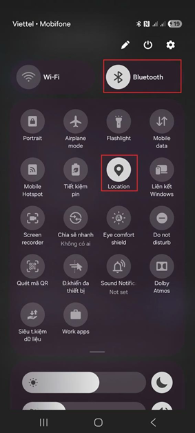 Figure 17. Grant all the permissions request by program


Grant all the permissions request by program as above
Connecting sensor
Run the application and select the sensor you want to connect to, as shown in the pictures below:
-
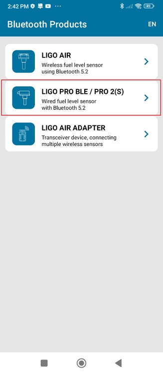 Figure 18. Selecting sensor type
 -
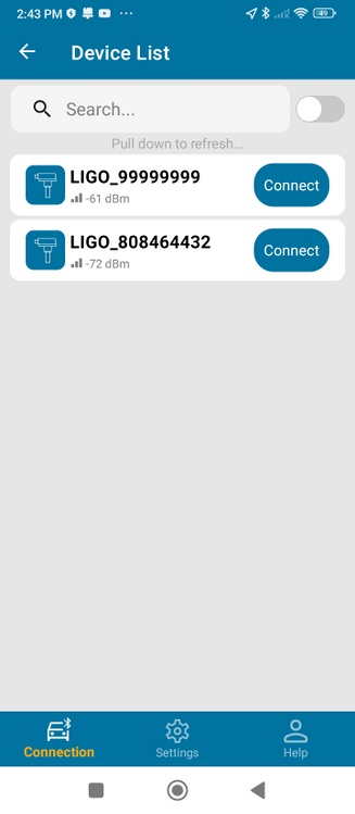 Figure 19. Connecting sensor


Set Empty and Set Full
Step 1: Set Full
- Immerse the sensor in fuel until the fuel reaches the sensor flange
- Wait for C_working value to stablize and then press Set Full button

Step 2: Set Empty
- Remove the sensor from the fuel and wait for 1-2 minutes allow the fuel drain from the measuring probe and then press Set Empty button.

Calibration table
After installation, the sensor must be calibrated to ensure accurate volume measurement. Calibration table can be performed either on the platform (server) or locally on the sensor.
- Calibration table on the Platform (Server): The sensor sends raw level values (ranging from 0 to 4095) to the server via the telematic device. The platform uses a calibration table to convert these values into volume (liters).
- Calibration table on the Sensor: The sensor directly sends volume values (liters) based on the internal calibration table.
Note: For LIGO AIR sensors, the manufacturer recommends performing calibration table on the platform.
Attention!
- The manufacturer is not responsible for product availability in case of non-compliance of requirements of this service manual, unauthorized service and repair; if device has damage or traces of opening of head's body, mechanical damage of the probe or the interface cable, as well as traces of corrosive acids, open flame, high voltage, lightning strikes or other natural factors.
Certification / Compliance
Refer to LIGO PRO BLE Certification & Approvals for current certificate status.
Support / Contact
| Channel | Detail |
|---|---|
| Company | SOJI ELECTRONICS.,JSC |
| Address | C50-LK13, Lot No. 09, New Urban Area, Le Trong Tan street, Duong Noi Ward, Ha Dong District, Hanoi City, Vietnam |
| Tel/Fax | +84 24 62 932 369 |
| contact@sojielectronics.com | |
| Website | sojielectronics.com |
Revision History
Loading revision history...